In part one, I talked about what a Delta is and showed my 3D printed articulating Delta arm. Since then I’ve created a frame to hold the arm and mount motors to it.
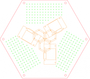
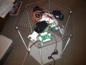
I used Adobe Illustrator to create the artwork for the top and bottom acrylic base pieces and brought the file over to SYN Shop for cutting.
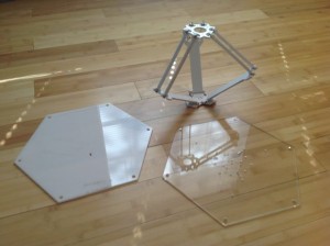
I used threaded rods at each of the 6 hexagon corners to hold the top and bottom pieces together.
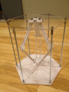
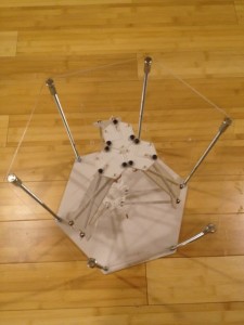
I used ViaCAD to create the mounting brackets for the servos and 3D printed them out. I ended up doing five revisions to get it right.
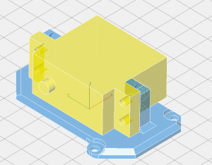
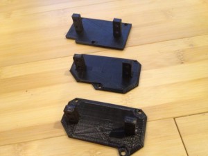
During the process of adding the servo motors I had to re-cut the plastic top to get a better fit for the servos, but also added a few hundred holes in a grid pattern to allow mounting of the electronics as needed. I picked up three standard servos at Pololu.com.
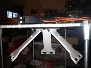
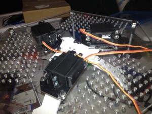
Next I started adding the electronics. I installed a Nymph board and a RobiCon connector fan-out board.
My next task was to write code. My first goal was to just get the servos moving to make sure that the way I was driving the actuators was sane. Here is the video below of the servos all being driven up and down in “thrust” mode.
Next time i will talk about the code that drives the Delta as well as more video showing the delta working.
One thought on “Delta Project – Part II”
Comments are closed.